How to Draw in Zx Plane in Abaqus
xix.four.ii The Sketcher sheet and grid

When you enter the Sketcher and either create a new sketch or edit an existing sketch, ABAQUS/CAE displays a sheet in the current viewport on which you sketch. In addition, the triad in the lower-left corner of the viewport indicates the orientation of the part or the assembly relative to the Sketcher sail. The sheet is always foursquare, and its tiptop and width are determined by the sheet size. ABAQUS/CAE determines the sheet size and the location of the origin, depending on what you lot are sketching:
-
If yous are sketching the base feature of a new function, the canvas size is the same equally the approximate size of the part that yous provided when you created the role. The origin of the canvas is located at the origin of the part'south coordinate system. Similarly, if yous are creating a stand-alone sketch, the sheet size is the same as the estimate size of the sketch that yous provided when you created the sketch.
-
If you are calculation a characteristic to a function or to the assembly, the default sheet size depends on the size of the face on which y'all are sketching. The origin of the sheet is located at the centroid of the selected face. If you selected a datum plane every bit the sketching aeroplane, the origin of the sheet is located at the centre of the office or assembly; the sheet size depends on the total size of the office or assembly.
Yous can utilize the Sketcher customization options to increase or decrease the sheet size if it does not correspond with the size of the geometry you are trying to sketch. To access the Sketcher customization options, select the customization tool ![]() from the Sketcher toolbox. You may need to use the magnify tool
from the Sketcher toolbox. You may need to use the magnify tool ![]() to view the entire Sketcher sheet inside the viewport.
to view the entire Sketcher sheet inside the viewport.
ABAQUS/CAE overlays the sail with a filigree of invisible grid points to help you position the cursor as you draw, move, resize, or reshape objects. By default, when you movement the cursor virtually a grid signal, the cursor automatically moves, or snaps, to the point. This behavior allows you to easily position the cursor precisely on a grid point while also providing you with total control when the cursor is not close to any grid points. If it is more convenient, you tin can disable the snapping behavior then that y'all have full control over the cursor. To aid yous visualize the grid points underlying the Sketcher grid, ABAQUS/CAE displays visible grid lines that pass through the grid points at a selected interval; for example, every other grid point.
For example, Figure xix–2 shows a canvas whose size is set to 100 and a filigree whose spacing is ready to 10 units.
Figure 19–two The Sketcher filigree.
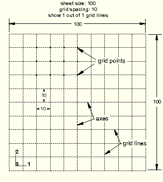
Every grid line in Effigy 19–2 is visible; the description, "ane out of x," corresponds to the customization option that allows you to instead brandish 1 out of 2 grid lines (every other), ane out of iii grid lines (every third), etc. In add-on, the Sketcher displays dashed lines along the grid indicating the X- and Y-axes of the sketch; the lines intersect at the origin of the sketch.
You tin can customize the appearance and behavior of the grid past choosing the spacing of grid points, the spacing of the visible grid lines that overlay the grid points, and the canvas size. You lot can also realign the grid relative to the sketch by moving the origin of the grid and by rotating the grid. Your sketch can extend beyond the Sketcher grid; however, if you find that you demand to sketch outside the grid, information technology is recommended that yous increase its size to include the unabridged sketch. If yous alter the grid origin or rotation, the Sketcher displays cursor coordinates in ii forms as you continue to modify the sketch. Grid coordinates bespeak the cursor position using the new filigree origin or rotation; sketch coordinates point the position based on the original grid location.
The analysis of your model can be afflicted by a loss of precision if the coordinates of a office are far from the origin of the part. For example, after y'all import a sketch to create the base feature of a part, the sketch may be relatively far from the Sketcher origin; as a result, the role will be far from its origin. To improve precision, you lot may accept to move the part closer to its origin past moving the sketch geometry closer to the origin of the Sketcher filigree using the translate tool, ![]() . Yous should non move the origin of the sketch closer to the geometry. Moving the origin of the Sketcher grid closer to the sketch is a graphical convenience simply and has no effect on the underlying precision of the coordinates.
. Yous should non move the origin of the sketch closer to the geometry. Moving the origin of the Sketcher grid closer to the sketch is a graphical convenience simply and has no effect on the underlying precision of the coordinates.

For information on related topics, click any of the following items:
-
"Turning snapping on or off," Department 19.9.2
-
"Customizing the sheet size and grid," Department 19.ix.4
-
"Basic Sketcher concepts," Section nineteen.iv
Source: https://classes.engineering.wustl.edu/2009/spring/mase5513/abaqus/docs/v6.6/books/usi/pt03ch19s04s02.html
0 Response to "How to Draw in Zx Plane in Abaqus"
Post a Comment